内容目录
This is the most watery article I've ever written
Device: Orange Pi H6, Pi 3
Pinout Diagram:
(Use WiringPi to view GPIO)
 +------+-----+----------+------+---+OrangePiH6+---+------+----------+-----+------+
 | GPIO | wPi |   Name   | Mode | V | Physical | V | Mode | Name     | wPi | GPIO |
 +------+-----+----------+------+---+----++----+---+------+----------+-----+------+
 |      |     |     3.3v |      |   |  1 || 2  |   |      | 5v       |     |      |
 |  122 |   0 |    SDA.0 | ALT2 | 0 |  3 || 4  |   |      | 5V       |     |      |
 |  121 |   1 |    SCL.0 | ALT2 | 0 |  5 || 6  |   |      | 0v       |     |      |
 |  118 |   2 |     PWM0 |  OFF | 0 |  7 || 8  | 0 | OFF  | PL02     | 3   | 354  |
 |      |     |       0v |      |   |  9 || 10 | 0 | OFF  | PL03     | 4   | 355  |
 |  120 |   5 |     RxD3 | ALT4 | 0 | 11 || 12 | 0 | OFF  | PD18     | 6   | 114  |
 |  119 |   7 |     TxD3 | ALT4 | 0 | 13 || 14 |   |      | 0v       |     |      |
 |  362 |   8 |     PL10 |  OFF | 0 | 15 || 16 | 0 | OFF  | PD15     | 9   | 111  |
 |      |     |     3.3v |      |   | 17 || 18 | 0 | OFF  | PD16     | 10  | 112  |
 |  229 |  11 |   MOSI.1 | ALT2 | 0 | 19 || 20 |   |      | 0v       |     |      |
 |  230 |  12 |   MISO.1 | ALT2 | 0 | 21 || 22 | 0 | OFF  | PD21     | 13  | 117  |
 |  228 |  14 |   SCLK.1 | ALT2 | 0 | 23 || 24 | 0 | ALT2 | CE.1     | 15  | 227  |
 |      |     |       0v |      |   | 25 || 26 | 0 | OFF  | PL08     | 16  | 360  |
 +------+-----+----------+------+---+----++----+---+------+----------+-----+------+
 | GPIO | wPi |   Name   | Mode | V | Physical | V | Mode | Name     | wPi | GPIO |
 +------+-----+----------+------+---+OrangePiH6+---+------+----------+-----+------+
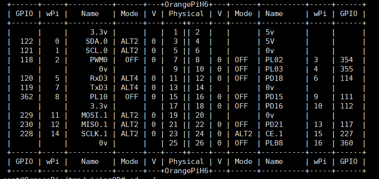
The following image shows the GPIO pin function diagram of the Orange Pi 3.

Activate the GPIO module
modprobe gpio-sunxi
Install the correct version of WiringOP
First, download and install git
apt-get install git-core
Download WiringOP
WiringOP is a version adapted from WiringPi, GitHub address https://github.com/orangepi-xunlong/WiringOP
git clone https://github.com/orangepi-xunlong/wiringOP.git
cd WiringOP
chmod +x ./build
sudo ./build
This completes the installation of the WiringPi version for Orange Pi 3.
Test if it is installed correctly
gpio readall
If the pinout diagram appears, it indicates normal installation.
Light up a small lamp
Randomly create a file named test.c
#include <wiringPi.h>
int main (void)
{
  int a=122;  //GPIO pin
  wiringPiSetup () ;
  pinMode (a, OUTPUT) ;
  for (;;)
  {
    digitalWrite (a, HIGH) ; delay (500) ;
    digitalWrite (a,  LOW) ; delay (500) ;
  }
  return 0 ;
}
The positive lead is connected to pin 3, with GPIO number 122, which can be changed at will.
The negative lead is connected to GND, pin 6.
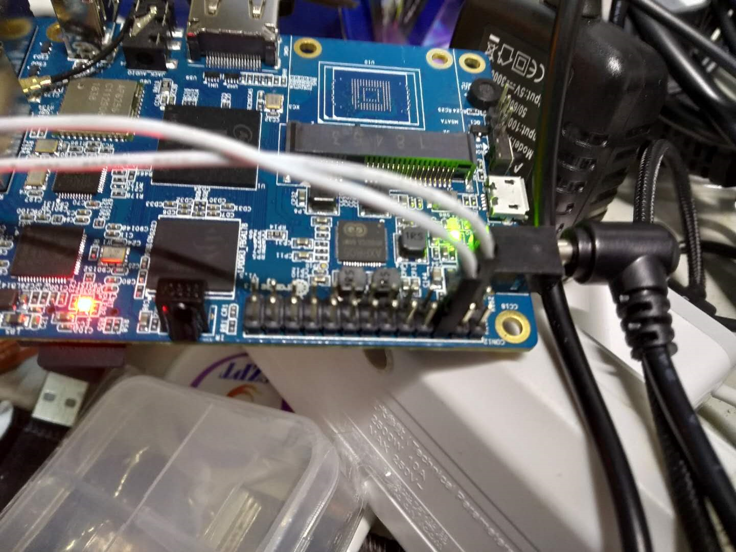
Compile and run
gcc -Wall -o test test.c -lwiringPi
sudo ./test
Don't buy Orange Pi.


文章评论